Alphanumeric
There is a 'need' to display the random target answer for the puzzle that the computer comes up with so people know if the computer solves the puzzle, or input the externally selected answer to the computer so it can solve the puzzle. My answer to this need started simple and slowly grew out of hand, step by step.
The simple solution is just let the computer select a randomized order for the boxcars to solve the Inglenook puzzle and display it on the laptop screen with the other graphics, which we do.

Thinking about the Inglenook layout and wanting to minimize cables I wanted to add WiFi between the layout and laptop as I have between the Train Thing laptop and layout. The Inglenook puzzle doesn't need the extra processor power or I/O of the Raspberry Pi like I used with Train Thing. Looking for something simpler, I found Adafruit's ESP323 Feather which has WiFi.
Other Feather/FeatherWing items include the Quad alphanumeric FeatherWing Display. One quad display could display which three boxcars on siding 2 are part a solution, and two quad displays could display which five boxcars on siding 3 would solve the puzzle.
I noticed that if I added a third quad display under siding 3, there would be the ninth character to display 'INGLENOOK'. And with two quad displays by siding 2, '.PUZZLE.' '.INGLENOOK..' could be displayed.
Breadboard of the alphanumeric displays with some display options.(More blue digits needed).
The simple schematic below is for the display next to siding 2 holding two quad alphanumeric displays. Holes in the circuit board are on 0.1" centers and represented by the circles. Grayed circles/holes are not used and shown for reference/spacing only. Each quad alphanumeric display plugs into 2 sixteen-pin receptacles on the circuit board. As shown the quad display has only 24 pins. Four of the pins are used: 2 for power, and 2 for the I2C, Inter-Integrated Circuit, control from the ESP323 Feather. Also note the 4 holes between the 16-pin receptacles. The displays overhang the receptacle and this spacing abuts two quad displays.
The schematic for the display next to siding 3 is similar, with a third pair of sixteen-pin receptacles/quad display connected in parallel on the left.

Not knowing how I was going to mount the displays on the layout, I put the layout in the middle of the blank board. I can 'cut to fit' later. The interconnecting wiring is on top of the board, protected under the quad displays.

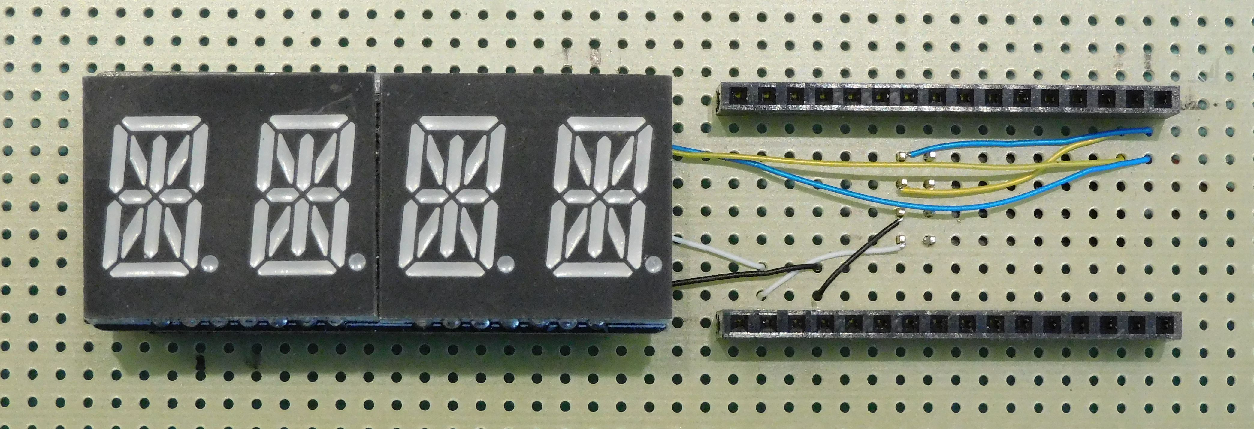
On the back of the circuit board are two 4-pin plugs used to connect the ESP323 Feather and the two quad display circuit boards.


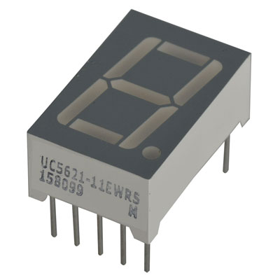
After much playing around with the quad displays, I've changed my mind. Instead of the short unevenly spaced labels identifying the target solution, I want something more aesthetically pleasing. An alternative is to adulterate Adafruit's product and USE cables TO locate single-digit 7-segment displays centered on the locations of the boxcar's 'parking' places.
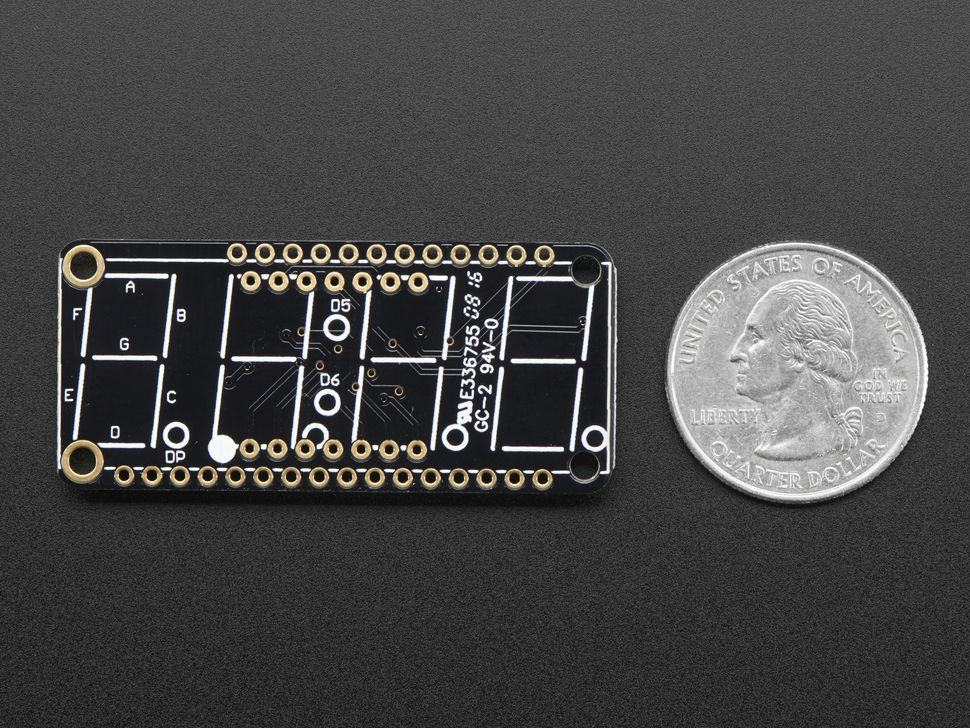
The 'Adafruit 4-Digit 7-Segment LED Matrix Display FeatherWing', the circuit board pictured below, is designed to have a 4-digit display mounted on the top, connected to the 2 rows of 7 holes on the board. The surface mount IC on the underside of the board multiplexes the four digits, displaying the stored segments for each digit. The 8 LEDs for each digit (7 segments, plus decimal point) are connected as common cathode. Cables for each single digit display will need to contain the 8 LED leads plus one of the four common cathodes. (The 14 pins connecting the 4-digit display are: 8 LED multiplexed pins, 4 common cathodes - one for each digit, and 2 pins to display the colon used to display time.)
On the underside of the circuit board are three solder pads, labeled A0, A1, A2. These pads are used to set the last digit of the of the board's I2C address to be different than all other elements on the I2C buss.

Below are the custom circuit boards to implement the new plan. On the left is the custom board that will plug in on top of the 4-Digit 7-Segment LED Matrix Display FeatherWing, replacing a 4-digit display. There will be two of these boards. There will be eight of the smaller circuit board on the right, one for each digit. Both diagrams are shown looking down on the top of the board.

On the FeatherWing custom board, the grayed elements are for reference/orientation only. The two 7-pin connectors show the location of the female receptacle added to the FeatherWing, replacing connection to the 4-digit display, and the matching male plugs on the underside of the custom board. The labels show the function of the fourteen pins. (The numbers 1, 7, 8, 14, are the 4-digit display pin numbers.) Across the middle are four 10-pin female receptacles connected to remotely located digits and a 2-pin female receptacle for the colon, part of the 4-digit 7-segment LED display (Not used ~ unless I think of something).

Pins 'A' - 'G' are connected to the anode of one of the 7-segment LEDs. 'DP' is the anode of the decimal point next to each digit. Pins labeled '1'-'4' are the four common cathodes, one for each digit. Pins 7 (anode) and 8 (cathode) are for the colon in the middle of the 4-digit display used to display time.
The circuit board on the right is to connect a single 7-segment LED digit to a cable from one of the FeatherWing custom boards. Two 5-pin female receptacles on top of the board match the pins on the LED. LED pin numbers 1, 5, 6, 10 are shown. The 10-pin male plug on the back of the board match the female end of the cable. The wiring shown between LED pins 3, 8, and the cable plug is the common cathode, numbered connection.
The inter-connecting cables are 9-wire extension cables, male on one end and female on the other. The tenth connection on the 2x5 cable ends is reversed pined: a blocked hole on the female end, and a missing pin on the male end. With matching connectors on the two custom boards, improper cabling should be harder.
Custom FeatherWing board wired.


4-Digit 7-Segment LED Matrix Display FeatherWing with 4-digit display replaced with two 7-pin receptacles for custom board that will sit on top.

Schematic/layout for the Numeric mother board.
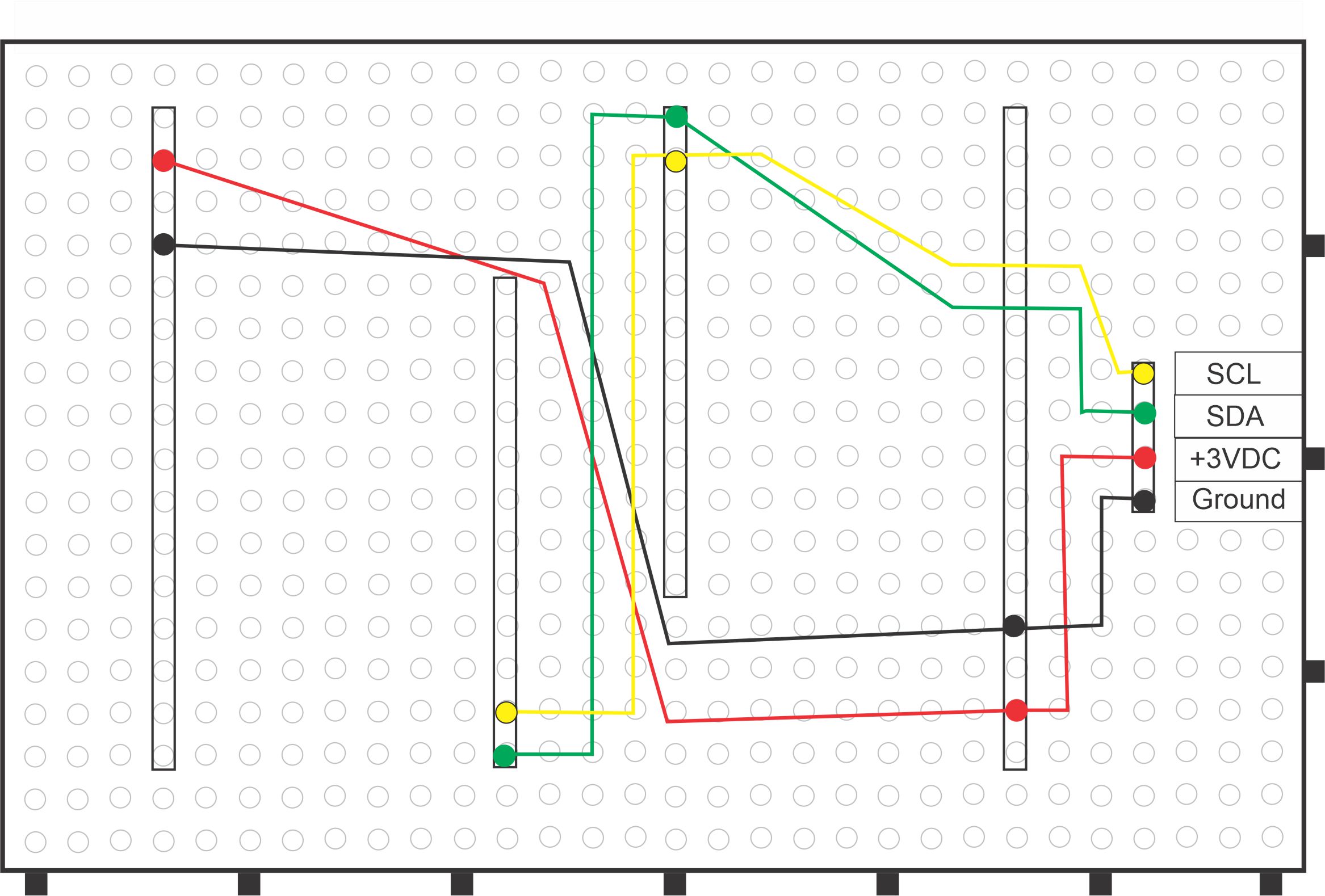
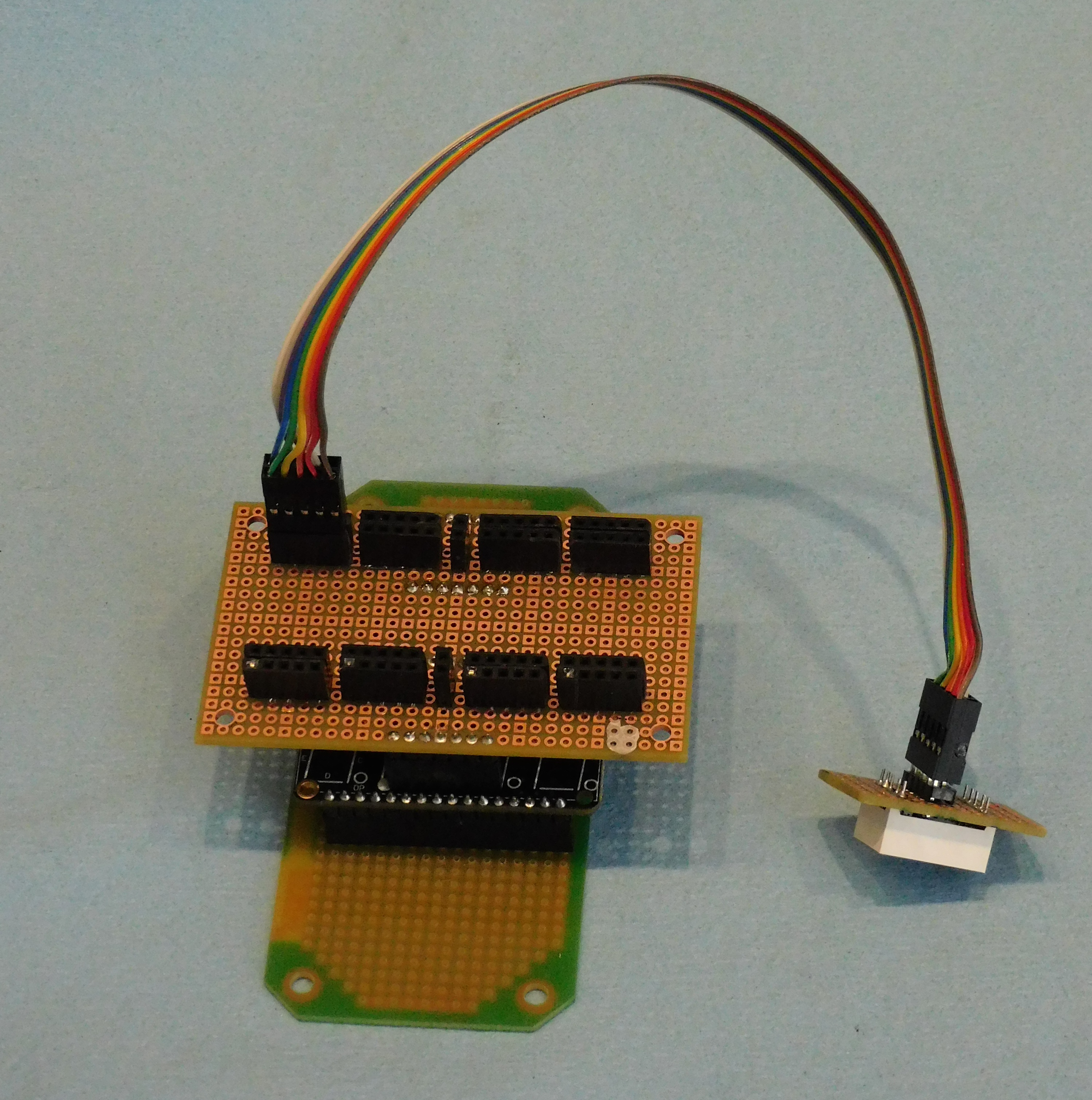
Putting this all together, first there is the Numeric mother board (green edge) with the two FeatherWing board attached. As shown in the schematic above there will be a 4-wire cable from the mother board providing the i2c connection to the ESP323 Feather.
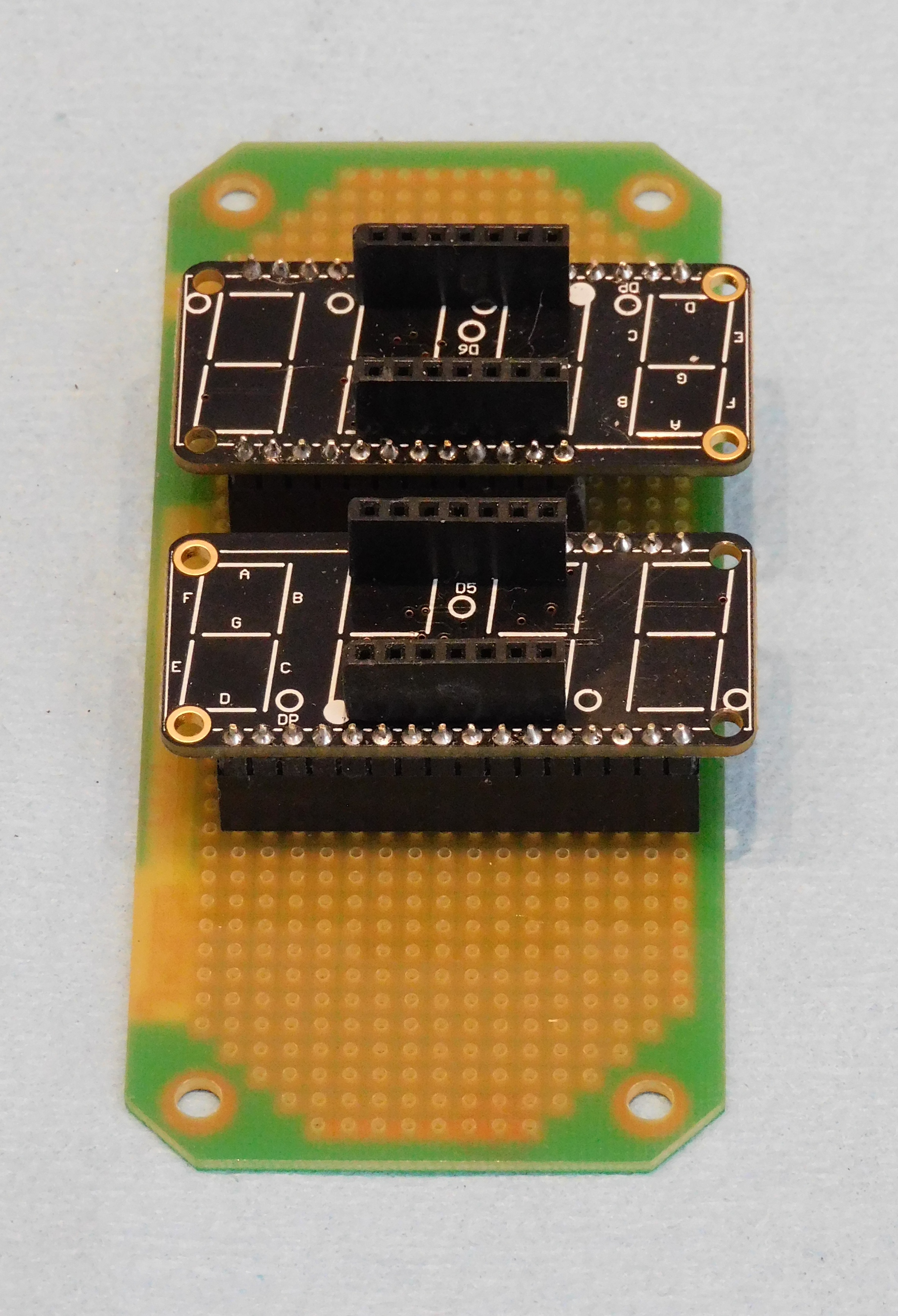
On top, plugged into the two FeatherWing boards replacing 4-digit alphanumeric displays is the Custom FeatherWing board with the 8 2x5 plugs, one for each digit. Test cabling to a single-digit 7-segment display is shown.
