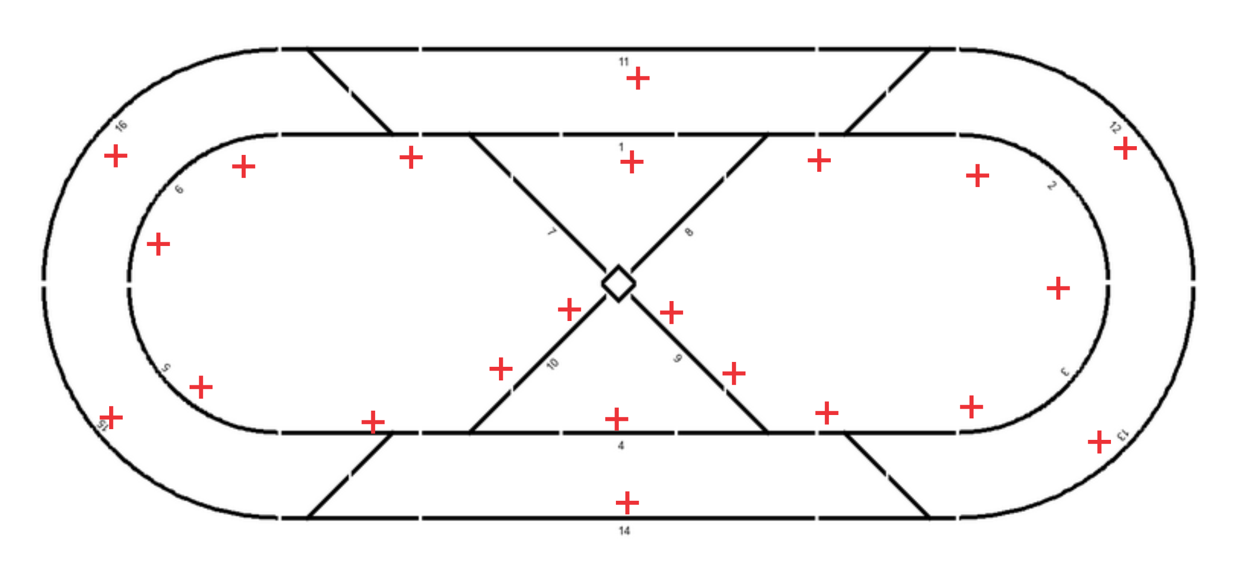
Two Isolated Track Blocks
An analysis of the track layout reveals that potential shorting problems, for all paths around the layout can be resolved by being able to reverse the polarity of blocks 7 and 8, labeled below.
The two ovals and switching between them don't present a problem if wired correctly. The "X" of the figure-8s does present a problem.
The problem presented by the figure-8s is solved by being able to reverse the polarity of blocks 7 and 8 while the train is in the block. The train must be completely within the block when reversing the polarity or a short will occur when a wheel rolls over the gap between reversed block and the last block, shorting them. To keep the overall all layout small, short blocks 7 and 8 is one of the advantages of the short wheelbase switchers, with no rolling stock.

There are several ways to analyze the track for potential shorts. Reducing the track to the smaller oval and "X" the figure-8 can be seen as two overlapping reversing-loops, one is illustrated below. Normally all of the reversing-loop is one block that can be reversed, allowing for the longest possible train. In our case, with only the short loco, only the short block 7 needs to be reversed. The same is true for the other "reversing-loop" and block 8. The figure-8 for the large oval also include blocks 7 and 8. Blocks 7 and 8 also resolve the reversing problem with an analysis similar to that used for the inter oval/figure-8.

Another suggested approach after laying the track, is to paint an old rolling stock (or a block of wood) with one side red and the other green. Push the train car around the track, marking with pieces of tape which side of the track the red side of the car is on. Blocks of track with tape on both sides identify issues to be resolved.
The same thing can be done using a diagram of the layout and tracing the track with your thumb and finger across the track, marking the diagram on the side your thumb traces.

If you trace the diagram above with your thumb on the inside of the ovals, you will see as you approach block 7 from below (block 9) your thumb will be on the top of block 7. However, when approaching from the top (block 6) your thumb will be on the other side of block 7. A similar analysis can be done for block 8. Other pairs of blocks would also work, for example blocks 7 and 10. I chose blocks 7 and 8 to reverse.
To control the polarity of the DCC signal going to blocks 7 and 8 I use two Arduino pins configured as outputs which control two 5vdc relays. Whether the Arduino (2) pins are active or not is controlled by the DCC++ Base Station using the <Z ..> commands from the laptop (4). The Arduino header and relay circuit are show here.
