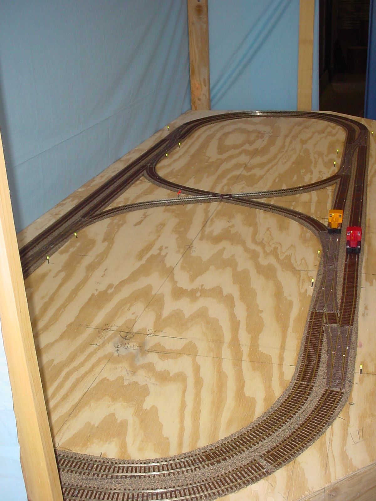
Track Layout
On the base near the points of each turnout there is a bi-color LED which reflects the state of the turnout: Green for CLEAR (Around the loop) or Red for THROWN (divergent path). The idea was to be able to see the state of each turnout while writing the software without getting up to look. The red/green doesn't photograph well.
Near the middle next to the crossover are two red LEDs. These show whether the polarity of blocks 7 or 8 are reversed. For block 7, (from the crossover, down to the left) if the LED of off the polarity is the same as the track from the crossover, up to the right. When the LED is on block 7's polarity matches the oval at the left end. See Two Isolated Track Blocks for why. Again the LEDs are so I can see the track block status while testing control software.

The location of the 36 IR sensors are shown in the drawing below, although not visible in the photo above.

