Installing Signals
Tomar Industries, who hand makes the semaphore signals, suggest drilling a 1/8" hole and using glue to hold the semaphore towers in place. My alternative installation is to drill a hole that gives a press to fit installation with no glue. The shaft of the semaphore tower is 0.092" in diameter. I used a #43 bit, 0.089", to drill the mounting hole which makes a solid snug fit.

 I use a short peace of dowel as a base to mount the signal tower on. This gets the mast above the cork roadbed. Think 'concrete signal pole base'. If I didn't hate to paint they would be painted Dorian Gray.
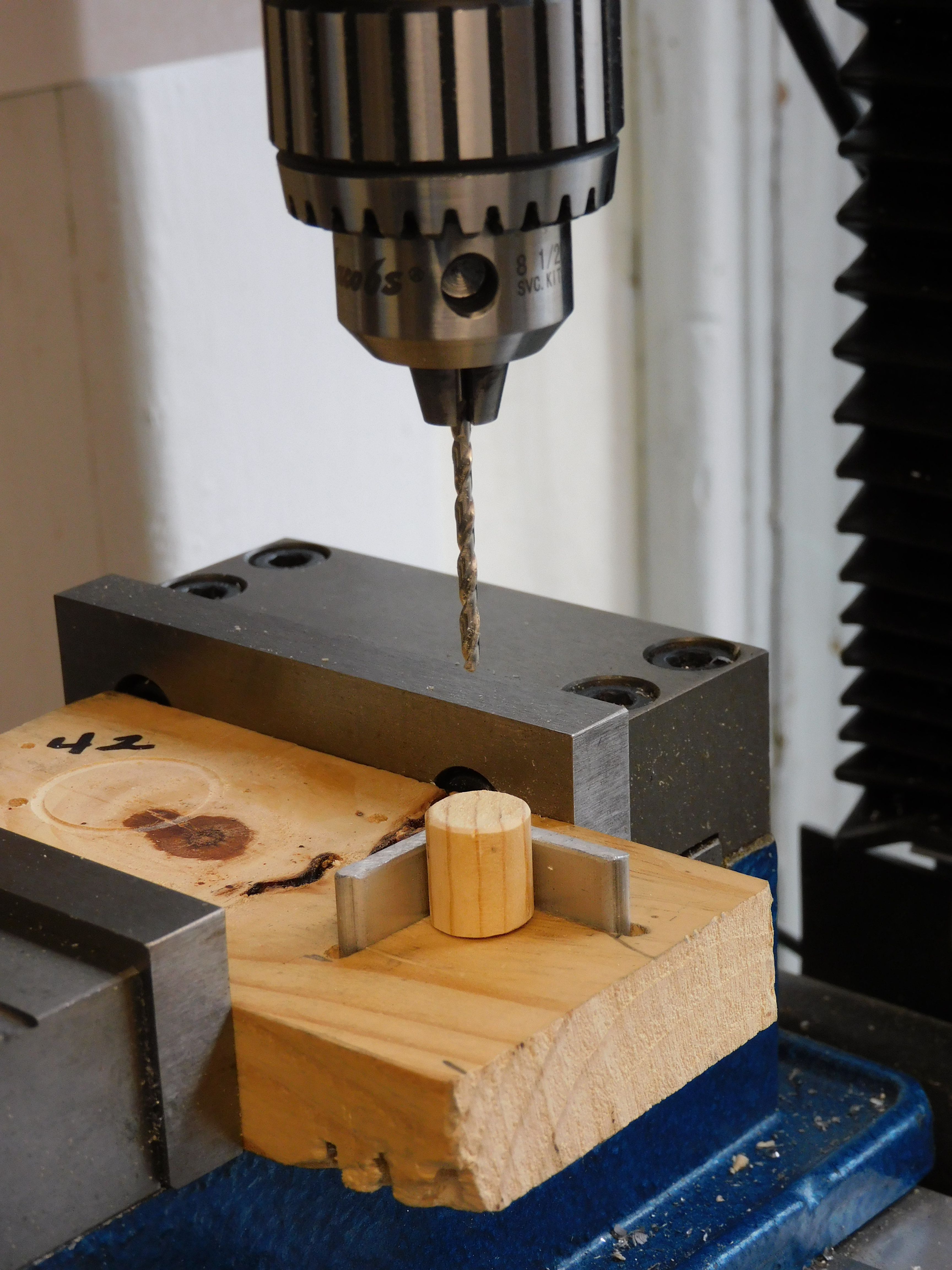
Using a vertical mill to drill the holes in the dowel is a bit of over kill but 1) I wanted the holes/towers to be straight up and down, 2) there are 30 to make, and 3) this is the tool I have.
A small piece of aluminum angle set in a wood scrap makes a jig to repeatably position the short wooden dowel for drilling.
I used a 1/2" Fotstner bit to get a flat bottomed hole in the cork roadway to prep where the dowel will be glued.

After a little bit of glue dries holding the dowel in place, I use the #43 bit to continue the mounting hole in the dowel down through the base. 
Using a loop of #28 wire to pull the LED wires down through the hole, then I press the semaphore into place, completing the top side phase of installation.

There should be a fourth signal pole in this cluster to 'control' movement between track blocks. The right hand track traveling for left up to the right should have a signal on the right side of the track. However, the semaphore arm would hang over the edge of the layout and would be damaged when the base is raised to work on the wiring underneath. The same is true at the left end of the layout.
With the base raised to access the underside, there is a problem. How do I connect the linkage that is on one side of the layout, while watching the controlled semaphore arm the other side of the layout? My answer is to use a USB camera pointed at the semaphores on the 'top' side, connected to a laptop on the 'under' side where I am making the connections. (The camera is next to the track pointed up at the semaphores.)

On the screen at the lower left you can see the semaphores (upside down). The screen on the upper right is tied to a Raspberry Pi running a test program to control the servo being installed/attached. 
Thing are crowed where blocks meet on both the inner and outer oval. Visible here are IR sensors #4 and #24 (two more are out of view above the photo), white/orange twisted wires providing DCC power to the track and one of the three brackets that go here. The holes with the scraggly wires are where the corner of the other two brackets need to be installed.
The small circuit board with the green connector, should be mounted on the bracket to provide power to the semaphore's LEDs but the wires are too short.
Near the inside corner of the bracket the hole through the layout can be seen. The two stiff wires controlling the semaphore arms are connected to the E-Z connectors just over the hole. These wires move about 1/8" from red to green aspect. 
Everything installed in the first cluster. Servo cable numbers are on both the servo plug and the end of the extension cable so that when you see both labels the plugs are orientated correctly. Also the low order wire in the plug is the ground. For example the yellow of yellow-green-blue cable is ground and connected to the brown wire from the servo. On the other end the servo control cables are connected to the Raspberry Pi (see Elements of the Stack), the labels are wrapped around the wires because there is not room on the plugs. The plugs are 0.10" thick and the pins they are plugged into are on 0.10" centers. Note below that cable #1 on the left, brown-red-orange, has the brown wire (ground) connected to the lower pin. Three brackets, six servos done. Twenty-seven brackets, fifty servos to go.


Raspberry Pi with all the signal servos wired.

