Pictures
The progress of the Train Thing visually all in one place. In the hardware section below are detailed pictures and diagrams of individual elements, mostly computer boards.

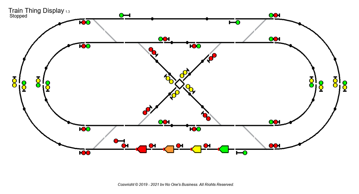
The basic track layout (from the Simulator). The black/green dots on the track are the logical location of the IR sensors. Numbers are the reference of the track blocks.

Same track with signals added. Will use three aspect semaphores. In the simulator searchlight signals are easier to display. The top signals are for the main line, bottom for divergent line. At the bottom in front of the four locos are "short" yard-signals used when the locos are in the "staging yard" at the beginning and end of a simulated or actual run. These four yard-signals will be vertical LED tri-lights.

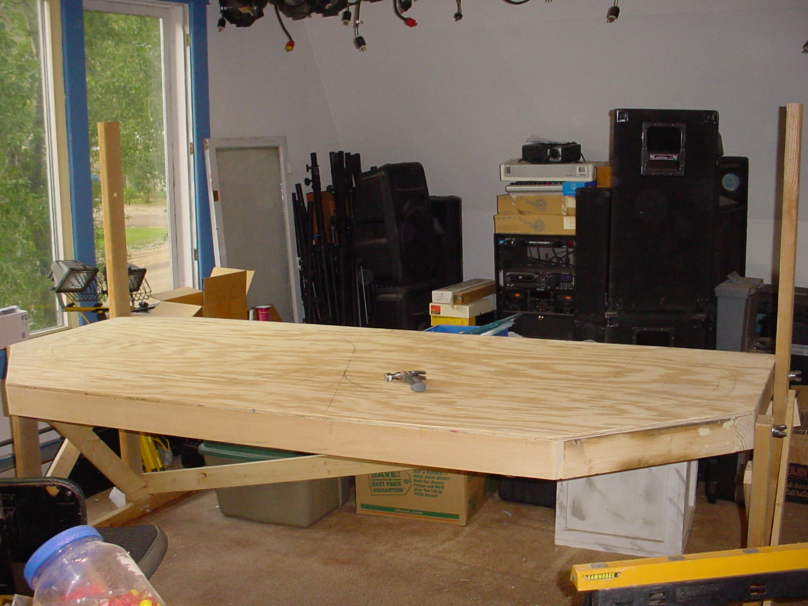
The track base in the up position to work on the wiring, etc.
And down so the locos don't fall of the track.


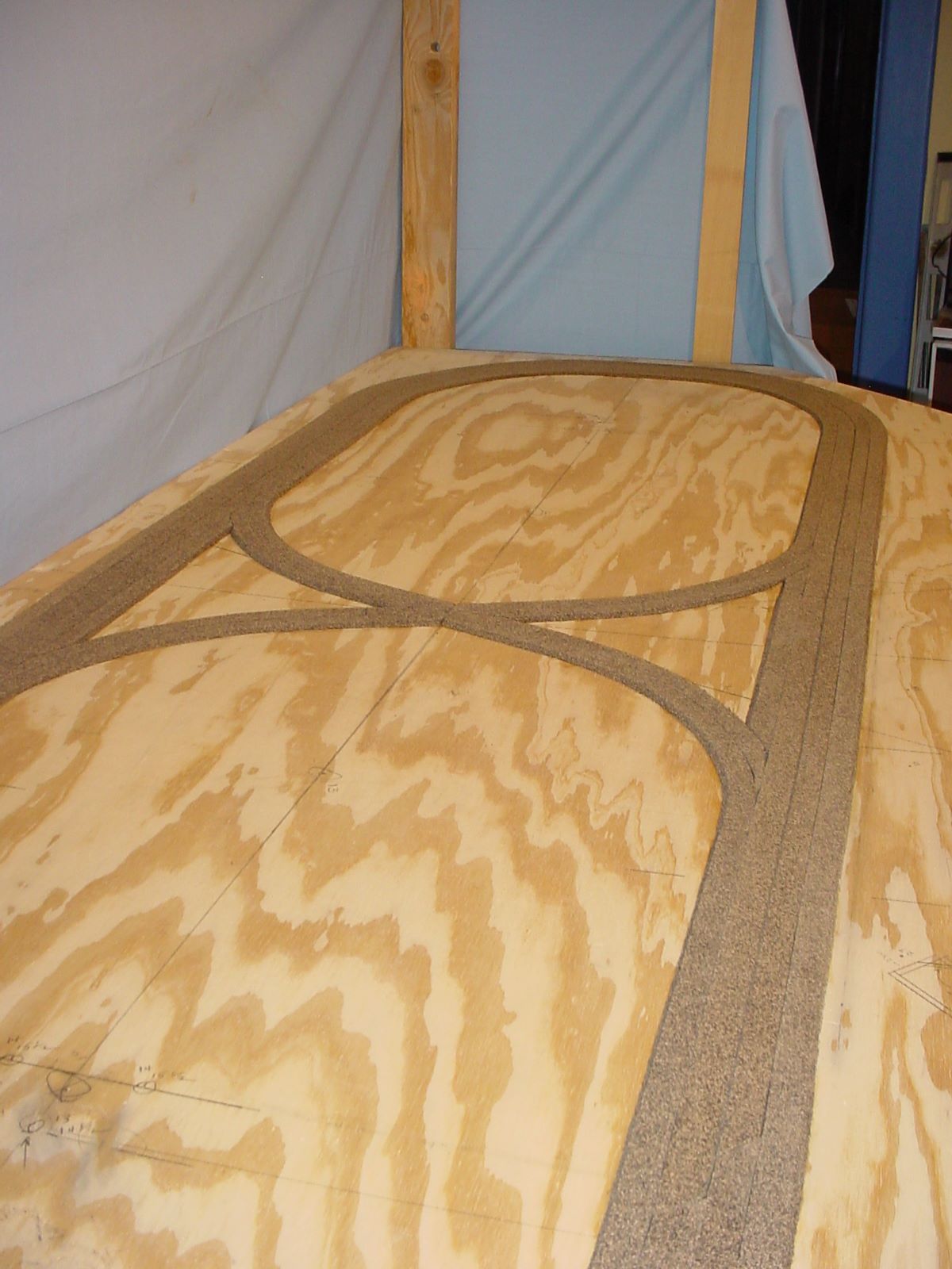
Base with the cork roadbed in place and with the tack. The blue backdrop is to hide the mess in the rest of the room.

Here is the wiring for all the DCC controlled track and turnouts. Signals will add 60 additional 3-wire cables.


On a back leg of the layout are the three DC power sources needed by the Train Thing.
5v0dc
18vdc
5vdc relay
to control
1v5dc

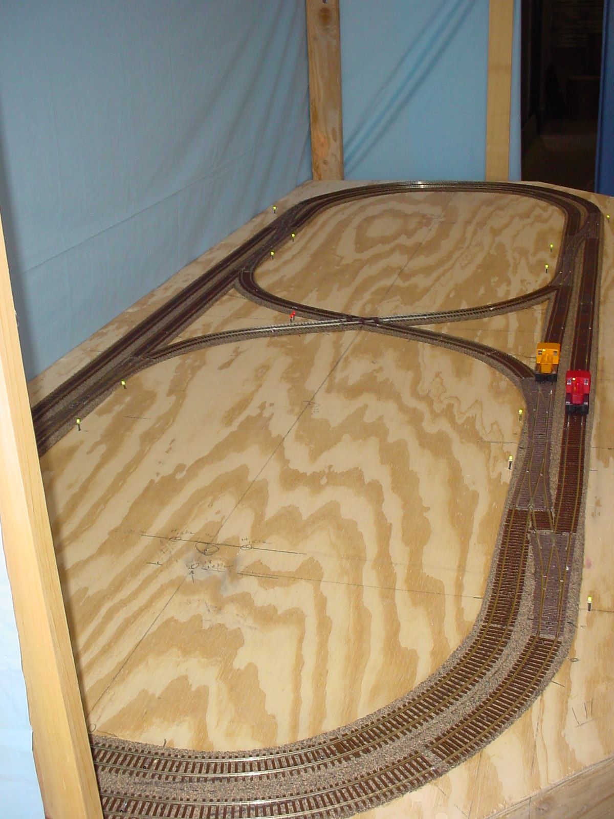
Except for Semaphores, I think the last hardware has been installed.
To the right of the four locos are the tri-light, low LED staging yard signals. Green on top, yellow and red on the bottom. (Railroads are different than traffic lights.)
Near the top alongside of the track can be seen small bi-color (red/green) LEDs that show the state of these three turnouts. One can also be seen behind the Green loco to the right. These have more to do with SW development than trains.
You can also see how a newbie lays what should be straight track. Next to the track are some black "dots" showing first cut of where the semaphores towers will be placed.

The wiring around the Arduino Base Station is ugly. However, I did need to get 36 3-wire cables from the sensors plus a 3-wire cable controlling the relays connected to the Arduino.
Space under the track is getting tight. This is under the straight track along the front of the layout. At the top is the "hidden" switch to change the parking lot from "Main track" to "Programming" mode. Under the bundle of rainbow cables are the four small (blue) IR sensor circuit boards for the four parking spaces (sensors #33, #34, #35 & #36). Sensor #27 is on the far right.
Below that, under the straight track for the small oval are a Tortoise, a Tortoise/Wabbit IO board, the four dwarf signal control boards, two more sensors and on the right another Tortoise. At the bottom of the picture is the Wabbit that controls the two Tortoises.

The Raspberry Pi (3) all wired up with unicorns and switches temporarily mounted. In the lower left corner of the unicorn display is the fan status, showing the temperature at step-2 on the ladder. All the LEDs around the track layout show stylized signal location.

With the Raspberry Pi (3) in place under the TrainThing layout, testing all the interconnections. On top the wide rainbow ribbon cable connects the two unicorn 16x16 matrix. To the left is the black 4-pin connector for the interrupts from the IOPi HAT to the voltage dividers and RPi GPIO pins. Below that is a green-black twisted pair supplying 5v0dc to drive all the servos (not connected) and 2 gray/blue ribbon cables connecting the Wabbits to the IOPi. On the right side of the RPi are cables connecting to the parking lot signals, fan switch and RPi-on LED. Across the front is a green-blue ribbon connecting two of the interrupts, a 4-wire rainbow ribbon to the right connecting the traffic monitor LEDs and another gray ribbon cable connecting additional Wabbits. The unconnected pins across the front are where the 56 servos to control the semaphores will be connected.
The small board, lower right, combines wires from the IOPi HAT, PWM HAT, RPi and resistors to connect to the switches and LEDs on the monitor display

Some of the semaphores installed where control blocks of track meet on the inner and outer loops. Under the layout are the brackets holding the servos that control the aspect of the semaphores.


Most of the 30 signal towers installed.

This is the underside of the TrainThing layout with most of the wiring finished.

Detail of the wiring to the Raspberry Pi.

This is the schematic of the TrainThing layout on the Laptop. All the turnouts are shown in the CLEAR position. Locos are shown in the staging yard with signals showing the correct aspect.

